Specifications: diameter: 320 to 127 mm thickness: 0.4 to 12.7 mm Length: 6 m above, and, in accordance with customer demand, supply and other specifications of steel pipe
Pipes Catalog
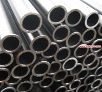
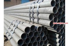
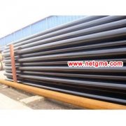
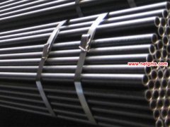
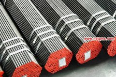
 Seamless steel pipe
- pipeline
- OCTG
- ASTM pipe
- API pipe
- Heavy Wall Steel Pipe
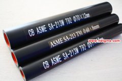
- Boiler steel pipes
- Casing and tubing
- Welded steel pipe
- spiral steel pipe
- ERW pipe
- SSAW pipe
- DSAW pipe
- LSAW pipe
- Carbon steel pipe
- Black steel pipe
- fluid pipe
- Pipeline Coating,2PE 3PE
- Structural steel pipe
- Mild Steel Pipe
- Alloy pipe
- galvanized steel pipe
- stainless steel pipe
- steel pipe schedule
- pipe fittings
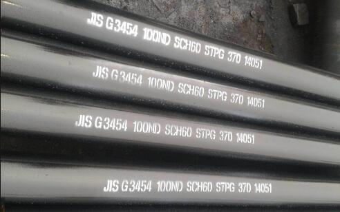
JIS G3454 Pressure Carbon Steel Pipe
JIS G3454 Carbon Steel Pipes for Pressure Service
1. Scope
This Japanese Industrial Standard specifies the carbon steel pipes, hereinafter referred to as the "pipes", used for pressure service at an approximate maximum temperature of 350℃. The pipes for high pressure service shall be in accordance with JIS G 3455.
Remarks
Pertaining to the electric-resistance welded steel tubes, when previously agreed upon with the manufacturer, the purchaser may designate the supplementary quality
requirements Z 3 or Z 4 specified in Appendix, in addition to the items specified in this text.
Appendix Z 3 Ultrasonic Examination
Appendix Z 4 Eddy Current Examination
The units and numerical values given in { } in this Standard are based on the international System of Units (SI) and are appended for informative reference.
Further, the traditional units accompanied by numerical values in this Standard shall be converted to the SI units and numerical values on Jan. 1, 1991.
2. Grade and Designation
Steel Grade: STPG 370 ,STPG 410
Steel Grade: STPG 370 ,STPG 410
The pipe shall be classified into two grades and their letter symbols shall be as given in Table 1
Table 1 Steel Grade:
| Letter symbol of grade | (Informative reference) Traditional letter symbol of glade |
| STPG 370 | STPG 38 |
| STPG 410 | STPG 42 |
3. Method of Manufacture.
The Method of manufacture shall be as follows:
3.1 The pipe shall be manufactured by either the seamless of the electric resistance welding process.
3.2 (Applicable till the end of 1990) The pipe shall stay as manufactured. However, the cold- finished steel pipe shall be annealed after manufacture.
The purchaser may specify heat treatment for the weld of the electric resistance welded steel pipe of grade STPG 42, as necessary.
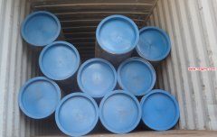
3.3 When required by the purchaser, the pipe may be furnished with a becwl end(1)
Note (1) Unless otherwise specified, the shape of the bevel end shall be as shown in Fig. 1.

4. Chemical Composition
| Letter symbol of grade | Chemical Composition % | ||||
| C | Si | Mn | P | S | |
| STPG 370 | 0.25 max. | 0.35 max. | 0.30 ~0.90 | 0.040 max. | 0.040 max. |
| STPG 410 | 0.30 max. | 0.35 max | 0.30 ~0.90 | 0.040 max. | 0.040 max. |
5. Mechanical Properties
5.1 Tensile Strength, Yield Point or Proof Stress and Elongation
The pipe shall be tested in accordance with 9.2 and the tensile strength, yield point or proof stress and elongation obtained shall comply with Table 3-1
|
Letter symbol of grade |
Mechanical Properties | |||||
| Tensile strength | Yield strength | Elongation % | ||||
| kgf/m㎡ {N/ m㎡} | kgf/m㎡ {N/ m㎡} | No.11 and No.12 test pieces | No. 5 test pieces | No. 4 test piece | ||
| Longitudinal | Transverse | Longitudinal | Transverse | |||
| STPG 370 | 38 {373}min | 22{216} min | 30 min | 25 min | 23 min | 28 min |
| STPG 410 | 42{412}min | 25{245} min | 25 min | 20 min | 19 min | 24 min |
Remarks.
1. When the tensile test is carried out for No. 12 or No.5 test piece for the pipe under 8mm in wall thickness, the minimum value of elongation shall be obtained by subtracting 1.5% from the values of elongation given in Table 3-1 for each 1 mm decrease in wall thickness, and rounding off to an integer in accordance with JIS Z 8401. Examples of calculation are given in Informative Reference Table1.
2. The values of elongation given in Table 3-1 shall not be applied to the pipe whose nominal diameter is 25A or smaller. However, the value of elongation shall be recorded.
3. In sampling the tensile test pieces from the electric resistance welded steel pipe, NO.12 or No.5 test piece shall be taken from the portion not involving welded seams.

Remark: 1 bar=10 5 Pa
Informative Reference Table 1.
Examples of Elongation Values Calculated for No.12 test piece (longitudinal) and No.5 test piece (transverse)taken from pipes under 8mm in wall thickness
| Letter symbol of grade | shape of test piece | Elongation value relating to wall thickness % | ||||||
|
Over 7mm
to and excl.8mm
|
Over 6mm
to and excl7mm
|
Over 5mm
to and excl.6mm
|
Over 4mm
to and excl. 5mm
|
Over 3mm
to and excl. 4mm
|
Over 2mm
to and excl. 3mm
|
Over 1mm
to and excl. 2mm
|
||
| STPG 370 | No12 test piece | 30 | 28 | 27 | 26 | 24 | 22 | 21 |
| No5. test piece | 25 | 24 | 22 | 20 | 19 | 18 | 16 | |
| STPG 410 | No12 test piece | 25 | 24 | 22 | 20 | 19 | 18 | 16 |
| No5. test piece | 20 | 18 | 17 | 16 | 14 | 12 | 11 | |
5.2 Flatness
When tested in accordance with 9.3, the pipe shall not generate flaws of cracks on its wall surface. In this case, the distance between the two plates shall be in accordance withthe following formula:
In the case of seamless steel pipe :
In the case of of electric resistance welded steel pipe:
for weld = H=(2/3)D
for the portion without weld = H=(1/3)D
where
H : distance between flattening plates (mm)
t : wall thickness of pipe (mm)
D :outside diameter of pipe (mm)
e : constant individual defined for each grade of pipe
0.08 for STPG 370
0.07 for STPG 410
5.3 Bendability For the pipe whose nominal diameter is 40A or smaller, In the test of 9.4 the pipe shall ve free from the occurrence of flaws or cracks on its wall surface, In this case the pipe shall be vent through 90ì around an inside radius that is 6 times its outside diameter
6. Hydrostatic Test of Nondestructive Test
The pipe shall be tested in accordance with 9.5 and the resulting hydrostatic characteristic or nondestructive characteristic shall conform to either of the following two. The
preference for which of them shall be left to the specification by the purchaser or to the discretion of the manufacturer.
6.1 Hydrostatic Test
When a hydrostatic pressure specified in Attached Table 1-1 or 1-2 is applied, the pipe shall withstand it without leakage.
6.2 Nondestructive Test
A nondestructive examination by either an ultrasonic test or an eddy current test shall be made on the pipe, and there shall be no signal greater than those produced by the artificial defects of the reference test block of division UD of the working sensitivity specified in JIS G 0582 or of division EY of the working sensitivity specified in JIS G 0583.
A nondestructive examination by either an ultrasonic test or an eddy current test shall be made on the pipe, and there shall be no signal greater than those produced by the artificial defects of the reference test block of division UD of the working sensitivity specified in JIS G 0582 or of division EY of the working sensitivity specified in JIS G 0583.
Hydrostatic Test Pressure
Unit: kgf/cm^2{bar}
| Schedule number Sch | 10 | 20 | 30 | 40 | 60 | 80 |
| Hydrostatic Test Pressure | 20 {20} | 35 {34} | 50 {49} | 60 {59} | 90 {88} | 120 {118} |
7. Appearance
7.1 The pipe shall be practically straight, and its both ends shall be at a right angle to its axis.
7.2 The inside and outside surfaces of the pipe shall be well-finished and free form defects that are detrimental to practical use.
8. Dimensions, Mass and Dimensional Tolerances
8.1 Dimensions and Mass
The outside diameter, wall thickness and mass of the pipe shall be as specified in Attached Table 2.
8.2 Dimensional Tolerances
The tolerances on the outside diameter and wall thickness of the pipe shall conform to Table 4. The length of a pipe shall be 4000mm or over.
Table 4. Tolerances on Outside Diameter and Wall Thickness
| Division | Tolerances on outside diameter | Tolerances on wall thickness |
|
Hot-finished seamless steel pipe |
40 A or under 【0.5mm |
Under 4mm
+0.6mm
-0.5mm
4mm or over
+15%
-12.5%
|
| 50A or over up to and incl. 125 A 【1% | ||
| 150A 【1.6mm | ||
|
200A or over 【0.8%
For the pipe of nominal size 350 A or over, the tolerances on outside diameter may be determined by the measurement of the length of circumference. In this case, the tolerances shall be 【0.5%.
|
||
|
Cold-finished seamless steel pipe and electric resistance welded steel pipe
|
25 A or under 【0.3mm |
Under 3mm
【0.3mm
3mm or over
【10%
|
|
32 A or over 【0.8%
For the pipe of nominal size 350 A or over, the tolerances on outside diameter may be determined by the
measurement of the length of circumference. In this case, the tolerances shall be 【0.5%.
|
Remarks
1. When the length of circumference is used in measuring the outside diameter, either the measured value of the length of circumference or the diameter derived form the measured value may be used as the criteria. In both cases, the same value (【0.5%】 of tolerances shall be applied. The diameter (D) and the length of circumference (ラ) shall be calculated reversibly from the following formula.
ラ=ヰ D
where ヰ=3.1416
2. In the case where the tolerances on wall thickness are confirmed to meet the specifications in the above table, the tolerances on outside diameter in the above table shall not be applied to the local part being subjected to repairing, etc.
9. Test
9.1 Chemical analysis
9.1.1 Chemical analysis
General matters common to chemical analysis and method of sampling specimens for analysis shall be in accordance with 3. in JIS G 0303.
9.1.2 Analytical Method
The analytical method shall be in accordance with one of the following Standards.
JIS G 1211
JIS G 1212
JIS G 1213
JIS G 1214
JIS G 1215
JIS G 1253
JIS G 1256
JIS G 1257

9.2 Tensile Test
9.2.1 Test Piece
The test piece shall be No. 11, No. 12 A, No. 12 B, No. 12 C, No. 4 or No. 5 test piece specified in JIS Z 2201 and shall be sampled from a pipe. In this case, the gauge length for No. 4 test piece shall be 50 mm.
9.2.2 Test Method
The test method shall be in accordance with JIS Z 2241.
9.3 Flattening Test
9.3.1 Test Piece
A test piece 50 mm or over in length shall be cut off from the end of a pipe.
9.3.2 Test Method
The test piece shall be placed between two flat plates at ordinary temperature and flattened by compression until the distance between the plates comes to the specified value,and checked for the occurrence of flaws of cracks on its wall surface. For the electric resistance welded steel pipe, the weld shall be placed at right angles to the direction of compression, and either the weld in case H=(2/3)D or the portion other than the weld in case H=(1/3)D shall be examined as shown in Fig. 2 and Fig. 3.
9.4 Bending Test
9.4.1 Test piece
A test piece with an appropriate length shall be cut off from the end of a pipe.
9.4.2 Test Method
The test piece shall be bent at ordinary temperature through the angle around a cylinder with the inside radius specified in 4.3, and checked for the occurrence of flaws or cracks
onit wall surface. In this case, for the electric resistance welded steel pipe, the weld shall be placed in the outermost bent portion.
9.5 Hydrostatic Test of Nondestructive Examination
The hydrostatic test or nondestructive examination shall be in accordance with either one of the following:
9.5.1 When the pipe is subjected to hydrostatic pressure and kept under the specified pressure, its strength to withstand the pressure without leakage shall be examined.
9.5.2 The test method of nondestructive examination shall be in accordance with either JIS G 0582 or JIS G 0583.
10. Inspection
10.1 Inspection
Inspection shall be as following:
General matters common to inspection shall be in accordance with JIS G 0303.
10.2 The chemical composition, mechanical properties, hydrostatic characteristic of nondestructive characteristics, dimensions and appearance shall conform to the requirements specified in 3,. 4,. 5,. 6,. and 7 However, appropriate nondestructive examinations other than those specified in 9.5 (2) may substitute as agreed upon by the purchaser and themanufacturer.
Further, when the supplementary quality requirements given in Appendix are specified by agreement between the purchaser and the manufacturer, the results of inspection shall conform to the requirements specified in Z 3 or Z 4.
10.3 Either the hydrostatic test of the nondestructive examination shall be performed for each pipe.
10.4 For the tensile test and flattening test of bending test, take pipes as test specimens as specified in Table 5 , and take one test piece from each test specimen.
Note (2) The expression "same dimensions" means the same outside diameter as well as the same wall thickness..
Table 5. Method of Sampling Specimen
| Division | Method of sampling specimen and number of test pieces |
| Nominal diameter, 50 A or under | On shall be taken form each 1000 pipes of its fraction of the same dimensions (2) |
| Nominal diameter, 65 A or over up to and incl. 125 A | one shall be taken from each 500 pipes or its fraction of the same dimensions |
| Nominal diameter, 150 A or over up to and incl. 300 A | One shall be taken form each 250 pipes of its fraction of the same dimensions |
| Nominal diameter, 350 A or over | One shall be taken form each 150 pipes or its fraction of the same dimensions |
Note (2) The expression "same dimensions" means the same outside diameter as well as the same wall thickness..
11.Reinspection
The pipe may be determined for final acceptance by a retest specified in 4.4 in JIS G 0303.
12. Marking
Each pipe having passed the inspection shall be marked with the following items. However, the smaller pipes or other pipes specified by the purchaser may be bundled together and marked for each bundle by a suitable means. In both cases, the order of arranging the marked items is not specified.
When approved by the purchaser, a part of the items may be omitted.
(1) Letter symbol of grade
(2) Letter symbol indicating the manufacturing processes(3)
(3) Dimensions( 4 )
(4) Manufacturer's name or its identifying brand
(5) Letter symbol denothing the supplementary quality requirement, Z
Note( 3 )
The letter symbol indicating the manufacturing processes(3) shall be as follows, provided that the dash may be omitted leaving a blank.
Hot-finished seamless steel pipe - S - H
Cold-finished seamless steel pipe- S - C
Electric resistance welded steel pipe other than hot-finished and cold -finished ones - E - G
Hot-finished electric resistance welded steel pipe- E - H
Cold-finished electric resistance welded steel pipe - E - C
Note( 4 )
The dimensions shall be expressed as follows.
Nominal diameter × Nominal wall thickness
Example: 50A × Sch 40, 2 B × Sch 40
13. Report
The manufacturer shall submit the test report when previously required by the purchaser.

Copyright (c)2012 LongtaidiIf you do not find the information you need, Click
Here Get Support
New Update Pipe List
-
Hot rolled seamless steel pipe production
Hot rolled seamless steel pipe production. Water line pipe
Water line pipe Size:4" to 60" carbon steel seamless pipeline, piplines,ERW line pipes,Spiral pipes.SSAW COATING PIPE LINE : [ Spiral Submerged Arc Welding (SAWH) steel pipeline]. API 5L Line Pipes X42
API 5L Line Pipes X42,API 5L: A25, A, B, X42, X46, X52, X56, X60, X65, X70, X80 API 5CT: J55 K 55 M65 N80 L 80 C 90 T 95 P110 H40 Q125 CS-90 SCS-95 SCS-80 TCS-110T . API 5l A53 ERW Pipe
API 5l A53 ERW Pipe,ERW steel pipe JCEO Wall thickness:0.5mm-25 ISO,TUV,AD,PED cert. GB/T3091-2001 Material include Q235 20# 16Mn(Q345,Q215) .
Contact Us Online To Serve You Better

Hot Click PRO
-
ASTM A106/A53 GR.B 32 INCH Carbon Seamless pipe
1. Carbon Seamless Steel Pipes of API 5L/ ASTM A106/A53 GR.B.2. Hot Expanded Seamless Steel Pipes.3. ERW Steel Pipe.. Thin-walled steel material parameters Reverse
Thin-walled steel material parameters Reverse,Advanced design and manufacture of the State Key Laboratory of auto body Hunan University, Changsha, 4100822. Abstract: identify the problem for thin-walled steel material parameters, using a. A53 SCH40 Welded Carbon Steel Pipe
A53 SCH40 Welded Carbon Steel Pipe, Grade: A53 GR. B, API 5L GRB, API 5CT GR. B, ST37, ST52 Outside Diameter: 1/2"-72" Wall Thinkness: 0.5mm-80mm sch40--schXXS.. ANSI steel pipe schedule chart - SCH40 SCH80 seamless ERW pi
ANSI steel pipe schedule chart - SCH40 SCH80 seamless ERW pipe .
- Carbon steel pipe Standard
- ASTM A106 pipe
- ASTM A53 pipe
- ASTM A192 pipe
- ASTM A252 pipe
- ASTM A179 pipe
- DIN 1629 pipe
- DIN 17175 pipe
- Alloy pipe Standard
- ASTM A335 pipe
- ASTM A210 pipe
- ASTM A213 pipe
- ASTM A234 pipe
- ASTM A519 pipe
- Stainless pipe metrial
- 304, 304L, 304SS pipe
- 310, 310S pipe
- 316, 316L pipe
- Pipe Fitting Metrial
- Carbon steel: A234 WPB pipe
- Stainless steel: 304,316 pipe
- Alloy steel: A234 WP5 WP9 WP11 WP22 pipe